The frequency-modulated continuous wave (FMCW) radar transmitter is designed to generate linear chirps with the following high-level specifications:
| Parameter | Value |
|---|---|
| Center frequency | 94 GHz |
| Maximum chirp bandwidth | 1 GHz |
Linear chirps over time with a center frequency of 94 GHz:
The radar transmitter is implemented with a Class A voltage-controlled 47 GHz oscillator with a varactor driven by a ramp voltage. The ramp voltage is generated digitally by an 8-bit counter register whose output feeds into an R-2R DAC. The output of the VCO is fed into a frequency doubler, and the resulting 94 GHz signal is amplified by the PA.
A center frequency of 94 GHz was chosen because Yahia, a graduate student advised by Prof. Niknejad, had recently taped out a 90 GHz PA in February 2023 and Prof. Niknejad suggested to use Yahia’s PA for this radar transmitter. As a result, the PA is courtesy of Yahia.
System Overview
Radar system-level diagram:
Unlike the other blocks on the chip, the radar transmitter has two dedicated power rails, VDD_RADAR and VDD_PA, that are not regulated internally and must be sourced externally. Nominally, VDD_RADAR should be 1 V, and VDD_PA should be 0.75 V.
Ramp Generator
The ramp generator is a digital circuit responsible for outputting an 8-bit ramp output that feeds into the R-2R DAC. Internally, there is a 32-bit counter register that is clocked by the CPU clock and used to generate the ramp output.
There are two states of the ramp generator: STATE_IDLE and STATE_RAMP.
- In
STATE_IDLE, the ramp generator waits forramp_generator_num_idle_cyclesclock cycles before it moves to theSTATE_RAMPstate. - In
STATE_RAMP, the ramp output is initially set toramp_generator_frequency_step_start. Everyramp_generator_num_cycles_per_frequencyclock cycles, the ramp output is incremented. Once the ramp output has been incrementedramp_generator_num_frequency_stepstimes, the ramp output is reset toramp_generator_frequency_step_start, and the state machine moves back to theSTATE_IDLEstate. The ramp is now complete.
The reason for allowing the CPU to set ramp_generator_frequency_step_start as well as ramp_generator_num_frequency_steps is that the varactor’s capacitance is non-linear with respect to the control voltage. Therefore, the control registers should be set, so that the ramp voltage causes the VCO to sweep linearly over the desired chirp bandwidth.
Ramp generator output:
R-2R DAC
The R-2R DAC converts the 8-bit ramp output from the ramp generator into an analog ramp voltage between 0 V and 1 V that controls the varactor in the VCO. The resistor values used are 1k and 2k.
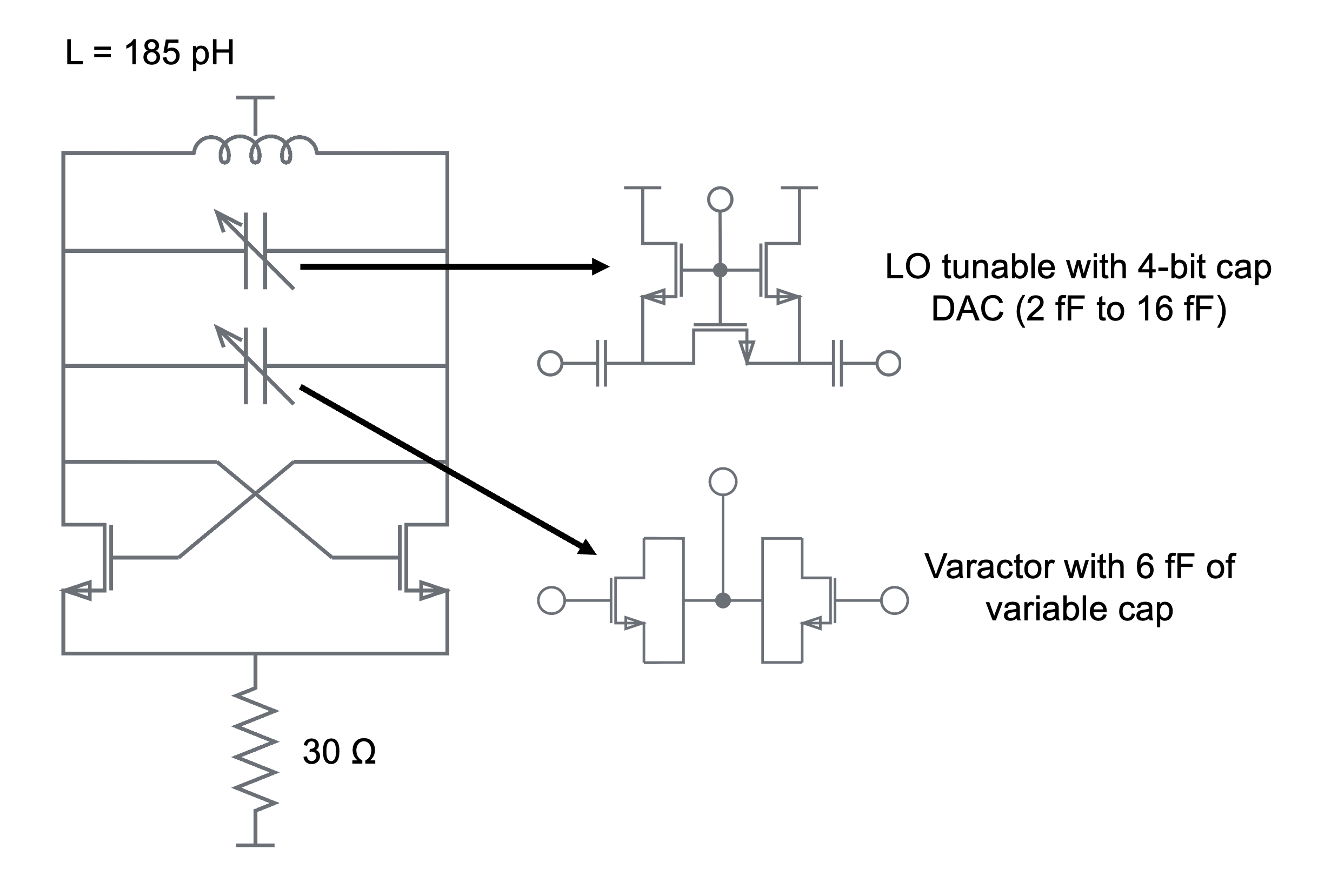
VCO
The VCO is a class A VCO with a 4-bit capacitive DAC ranging from 2 fF to 16 fF. Unlike the capacitive DAC, where a higher tuning code corresponds to a lower frequency, the varactor’s capacitance decreases as a function of the control voltage. However, since the frequency is sensitive to the control voltage, the control voltage is not brought out as a debug signal. In simulation, the VCO draws about 7 mW of power.
VCO schematic:
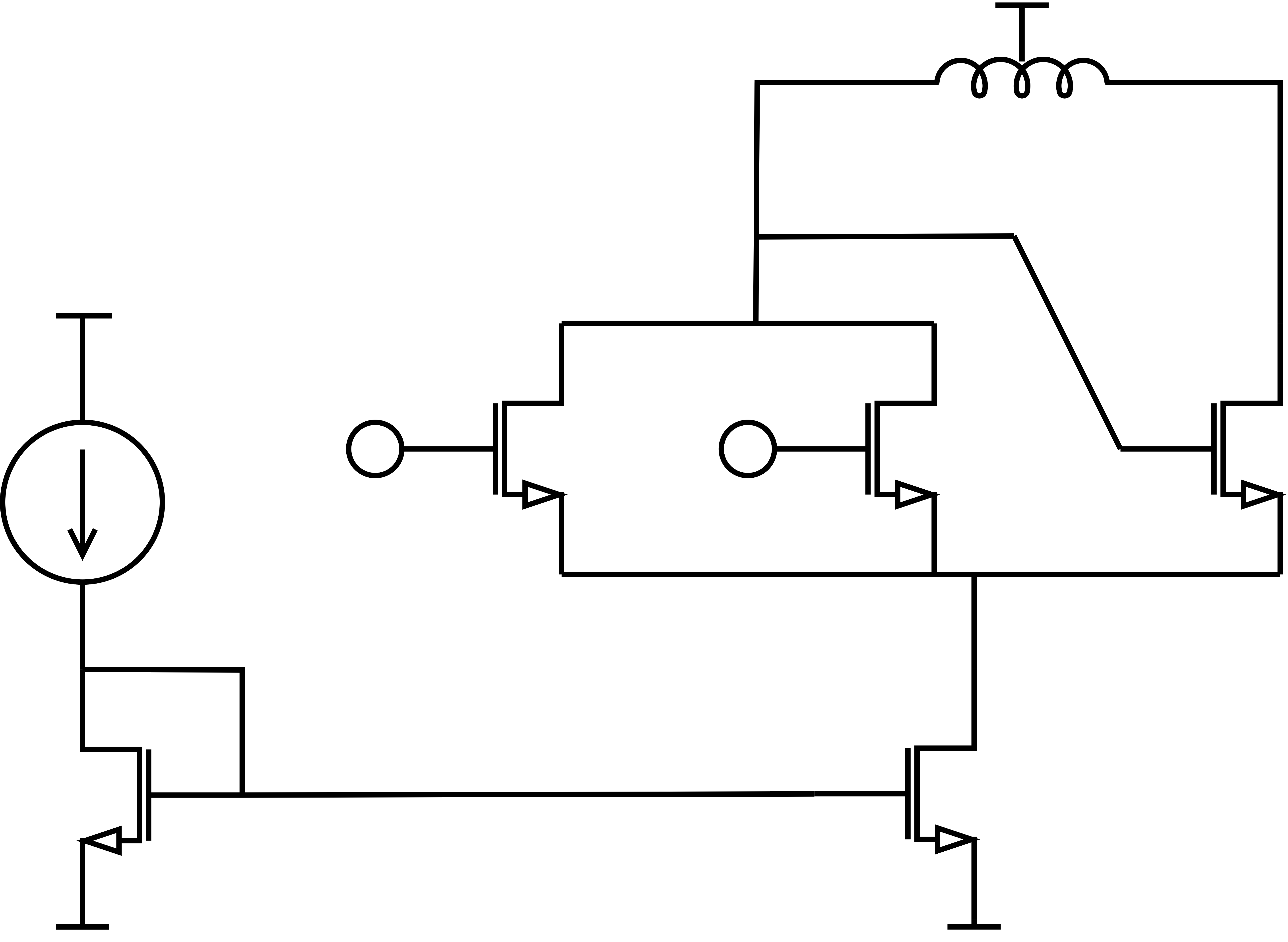
Frequency Doubler
The frequency doubler uses a modified cross-coupled pair with a resonant LC tank to double the VCO output’s frequency. In simulation, the frequency doubler draws about 16 mW of power.
Frequency doubler schematic:
PA
The PA was designed and laid out by Yahia with minor modifications for SCuM-V23. The PA consists of a driver stage and an output stage and consumes up to 60 mA at a supply voltage of 0.75 V.
Register Map
The radar configuration registers are part of the Scumvtuning block, which contains a set of memory-mapped registers for tuning analog blocks. The base address of Scumvtuning is 0x0000_A000.
| Register | Name | Size (bits) | Function |
|---|---|---|---|
0x0D | ramp_generator_clk_mux_sel | 1 | Unused. |
0x0E | ramp_generator_enable | 1 | Initial 1b'1.Enables the ramp output. |
0x0F | ramp_generator_frequency_step_start | 8 | Initial: 8b'0.Sets the initial ramp output for each ramp. |
0x10 | ramp_generator_num_frequency_steps | 8 | Initial: 8b'0.Sets the number of LSBs the ramp output should increment by for each ramp. |
0x11 | ramp_generator_num_cycles_per_frequency | 24 | Initial: 24b'0.Sets the number of clock cycles before incrementing the ramp output. |
0x14 | ramp_generator_num_idle_cycles | 32 | Initial: 32b'0.Sets the number of clock cycles to idle between ramps. |
0x18 | ramp_generator_rst | 1 | Initial: 32b'1.Resets the ramp generator’s counter and ramp output. |
0x19 | vco_cap_tuning | 5 | Initial: 5b'0.Tunes the 4-bit capacitive DAC of the VCO. The MSB is unused. |
0x1A | vco_enable | 1 | Initial: 1b'1.Unused. |
0x1B | vco_div_enable | 1 | Initial: 1b'1.Unused. |
0x1C | pa_enable | 1 | Initial: 1b'1.Unused. |
0x1D | pa_bypass | 1 | Initial: 1b'0.Unused. |
0x1E | pa_input_mux_sel | 1 | Initial: 1b'0.Unused. |
Layout
Final radar layout: The total area is 300 um x 200 um.