Radio
Radio Architecture
The radio operates within the frequency range 2.4 to 2.4835 GHz covering 70 1MHz RF channels. The receive chain should be sensitive to an input power range of -70 dBm to -10 dBm and achieve a BER of 0.1% or an SNR of 12.5 dB.
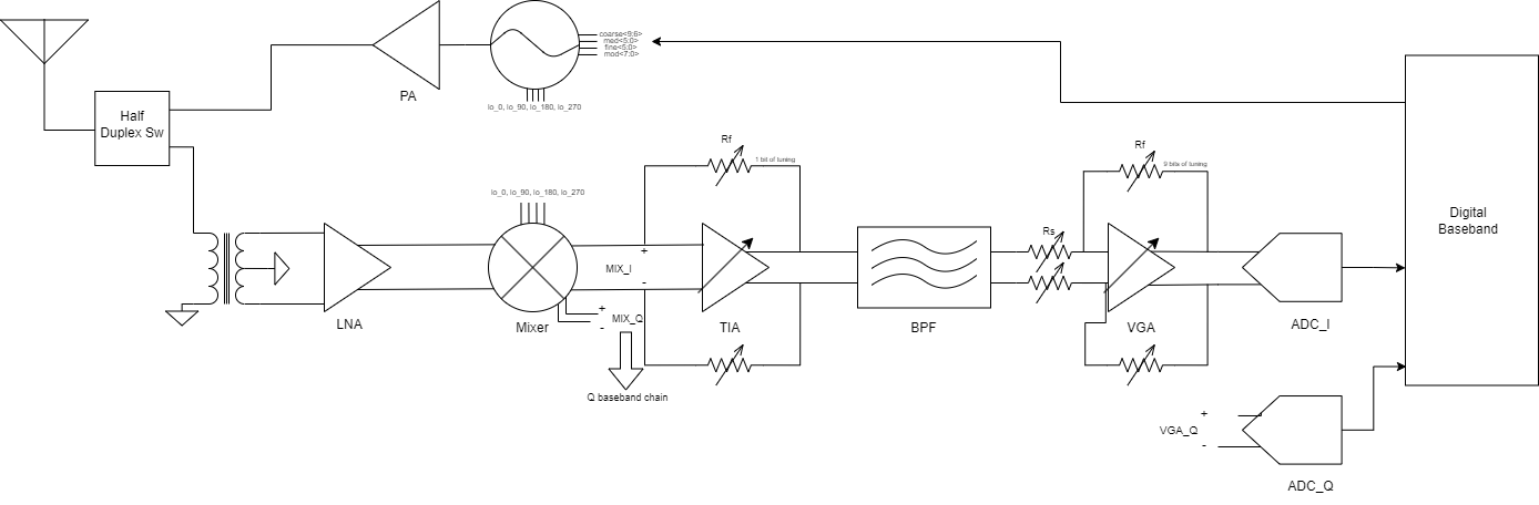
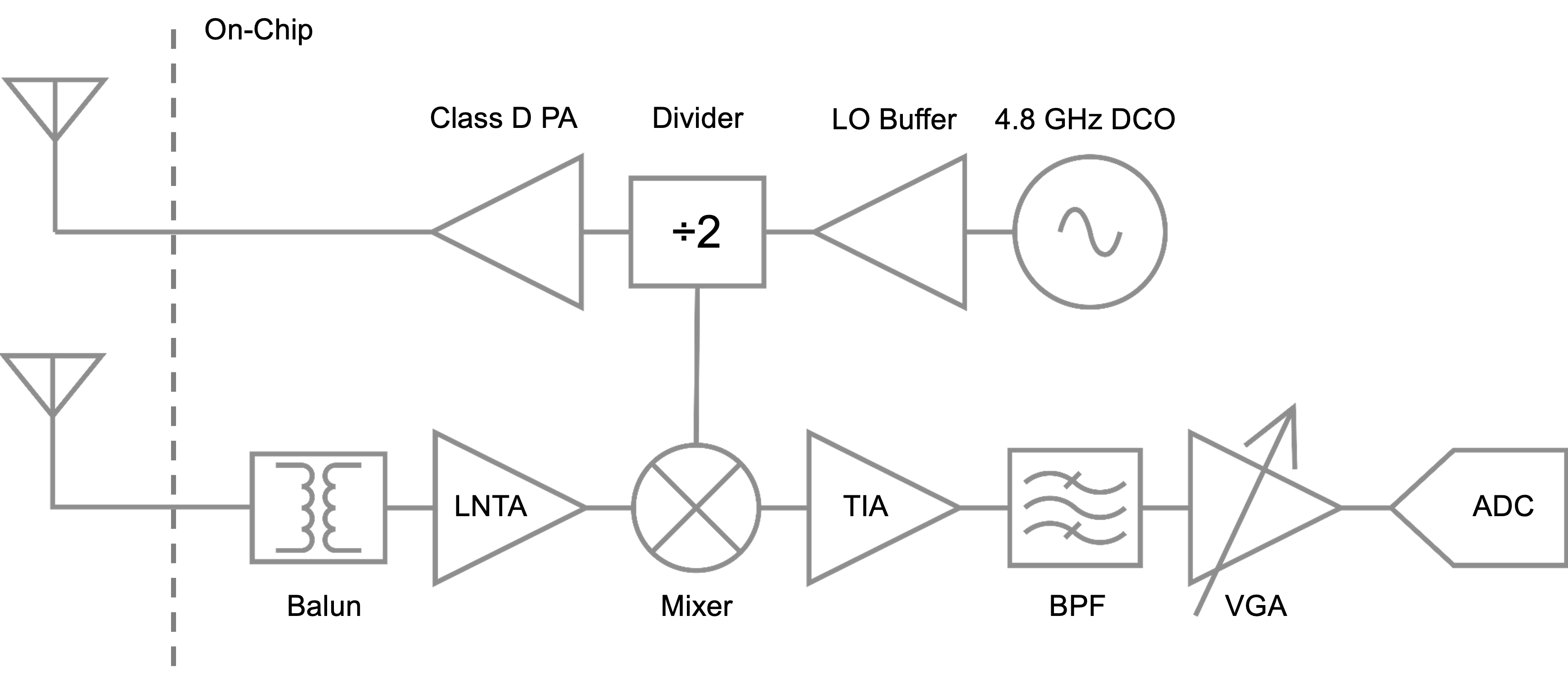
Radio Final Block Diagram
System Overview
The SCuM-V23 radio subsystem includes:
- Low Noise Amplifier (LNA): Provides initial signal amplification
- Mixer: Frequency down-conversion for baseband processing
- Transimpedance Amplifier (TIA): Current-to-voltage conversion
- Bandpass Filter (BPF): Channel selection and filtering
- Variable Gain Amplifier (VGA): Adjustable signal amplification
- Voltage Controlled Oscillator (VCO): Local oscillator generation
Transmitter
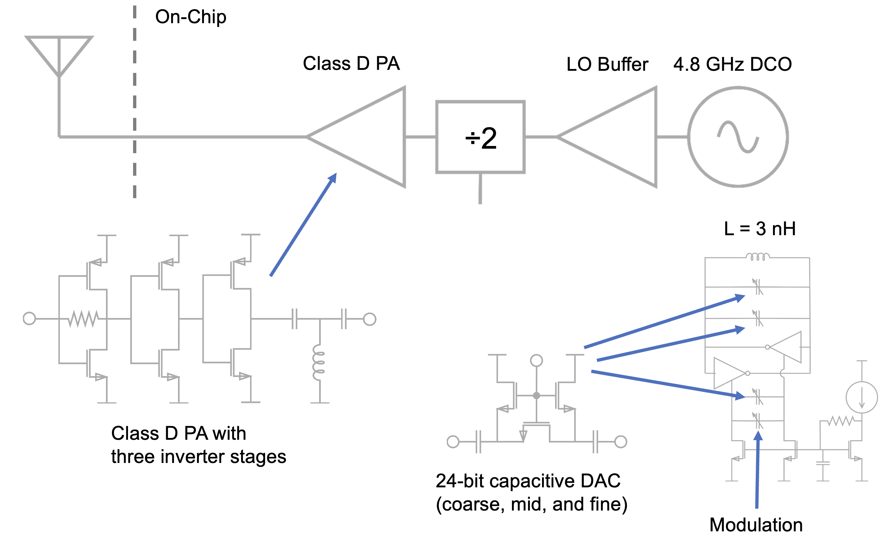
The transmitter is designed to operate in the 2.4 GHz ISM band and be standards-compliant with IEEE 802.15.4 and BLE. The tuning range of the 4.8 GHz DCO is 4.88 GHz ± 0.5 GHz with less than 40 ppm of resolution (less than 192 kHz), corresponding to 2.44 GHz ± 0.25 GHz after the divider.
Transmitter schematic: The divider divides the 4.8 GHz DCO signal down to 2.4 GHz and also generates the differential in-phase and quadrature components for the mixer.
System Diagram
The radio system is optimized for low-power operation while maintaining sufficient sensitivity for IoT applications.
Key Specifications
| Parameter | Value |
|---|---|
| Frequency Range | 2.4 - 2.4835 GHz |
| Number of Channels | 70 × 1MHz |
| Sensitivity | -70 to -10 dBm |
| Target BER | 0.1% |
| Required SNR | 12.5 dB |
| VCO Tuning Range | 4.88 GHz ± 0.5 GHz |
Design Considerations
- IEEE 802.15.4 and BLE compatibility
- Low power consumption for battery operation
- Integrated antenna interface
- Digital control for frequency selection
- Optimized for single-chip integration
For detailed register maps and configuration information, refer to the complete system documentation.