FPGA Programming
Complete guide for programming and configuring the FPGA for SCuM-V development.
Prerequisites
- Vivado 2025.1 (Recommended and tested)
- Arty A7-100T FPGA board
- Proper hardware connections (see Hardware Setup)
This guide is tested with Vivado 2025.1 on Windows. Other versions may work but compatibility is not guaranteed.
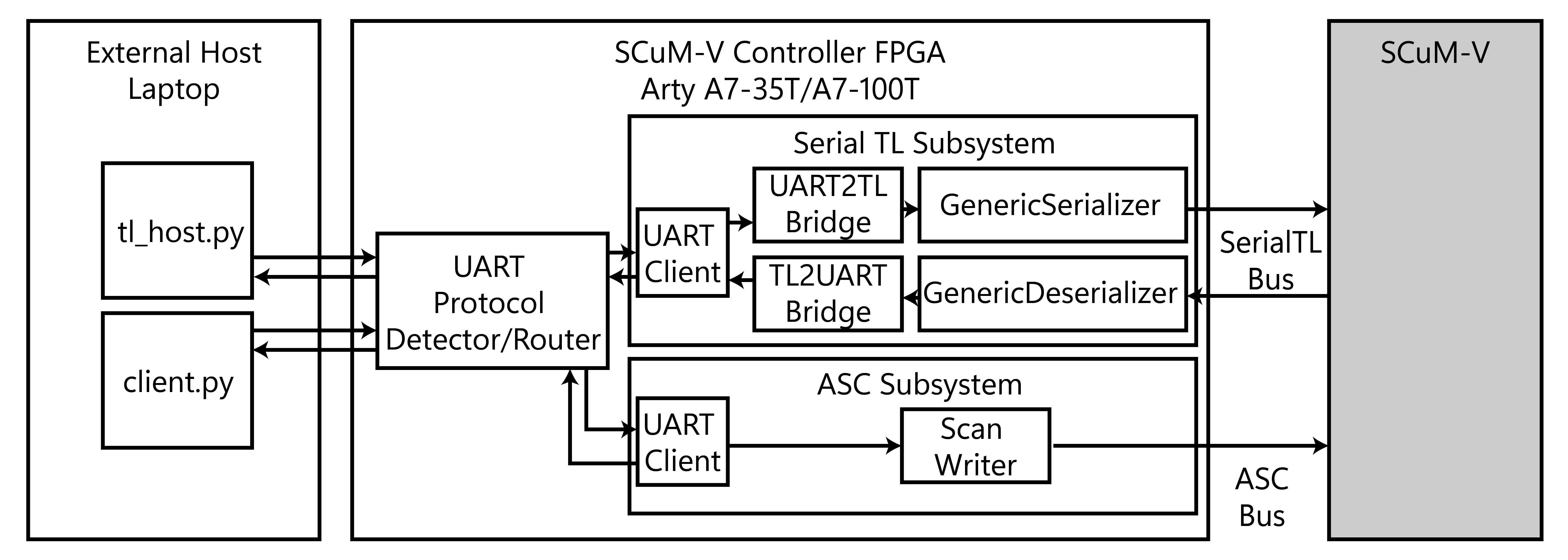
SCuM-V Controller Setup (Recommended)
The SCuM-V Controller FPGA implementation supports both SerialTL (digital interface) and Analog Scan Chain (ASC).
Project Structure
- create_project.tcl
Quick Start
Open Vivado 2025.1
Launch Vivado and prepare for project creation
Navigate to Project Directory
cd C:/path/to/scum-v-bringup/hw/scumv-controllerGenerate Vivado Project
source create_project.tclBuild Bitstream
In Flow Navigator: Generate Bitstream
Wait for compilation to complete
Program Device
- Connect Arty A7-100T via USB
- Flow Navigator →
Open Target→ Select Arty A7-100T Program Device- Verification: LED2 should turn on (indicates SCAN_CLK activity)
Alternative: Vivado GUI Workflow
If you prefer the graphical interface:
cd hw/scumv-controller
source create_project.tcl
Then use the Vivado GUI for synthesis, implementation, and programming.
Legacy Scanchain Implementation
The scanchain-only implementation is legacy/optional. Use SCuM-V Controller for full functionality.
For ASC-only UART adapter:
Navigate to Legacy Project
cd C:/path/to/scum-v-bringup/hw/scanchainGenerate Project
source create_project.tclFollow Build and Programming
Follow same build and programming steps as above
Simulation Environment
SCuM-V Controller Simulation
Primary Testbench: hw/scumv-controller/sim/scumv_controller_integration_tb.v
Configuration:
- UART Baud Rate: 2,000,000
- Test Vectors: Generated with
sw/tl_host_sim.py - Documentation: See
hw/scumv-controller/sim/TEST_VECTORS_README.md
Features:
- Console Logging: Testbench mirrors prints to
scumv_controller_integration_tb.log - Flow Control: Models backpressure by deasserting TL input ready intermittently
- Comprehensive Testing: Supports read/write/mixed transaction patterns
Test Vector Generation
Generate custom test patterns:
cd sw
python tl_host_sim.py
This creates binary test files for simulation:
single_read_test.bin- Basic read operationssingle_write_test.bin- Basic write operationsstl_mixed_5pkts.bin- Mixed read/write transactionsstl_flash_stress_4096pkts.bin- Stress testing
QSPI Flash Programming (Optional)
For persistent FPGA configuration across power cycles:
Prerequisites
- Successful bitstream generation
- Reference: Arty Programming Guide
Flash Device Selection
Important: Most new Arty A7-100T boards use s25fl128sxxxxxx0-spi-x1_x2_x4 flash device. Verify your specific board’s flash type.
Programming Steps
Generate Configuration File
- In Vivado:
Tools→Generate Memory Configuration File - Select appropriate flash device
- Generate
.binfile
Program Flash
Tools→Program Flash- Select generated
.binfile - Program and verify
Version Control Integration
Tcl Script Generation
For maintaining version control compatibility:
-
Generate Project Script
File→Project→Write Tcl...- Uncheck “Copy sources to new project”
- Save as
create_project.tcl
-
Clean Generated Script
- Remove references to
*.dcpfiles - Remove
utils_1folder references - Fix file paths:
${origin_dir}/../../[path]→${origin_dir}/[path]
- Remove references to
This workflow based on FPGA Developer’s Version Control Guide with updates for current Vivado versions.
Testing & Verification
Basic Functionality Test
Program FPGA
Load SCuM-V Controller bitstream onto the device
Verify LED2 Activation
Confirm SCAN_CLK indicator LED2 turns on
Check UART Interface
Ensure COM port is detected by your system
For detailed communication testing and firmware loading, proceed to the Bootloading Guide →.
Next Steps: Bootloading Guide → - Load and execute firmware on SCuM-V