µV-Precision Delta-Sigma ADC
The µV-Precision ADC is designed to function as an EEG front-end with high-level specifications:
| Parameter | Value |
|---|---|
| Resolution | 18 bits |
| Noise | 1.0 µVrms |
| Input Bandwidth | 500 Hz |
| Spot Noise | 45 nV/√Hz |
The ADC is implemented with a delta-sigma architecture, leveraging a high oversampling ratio to achieve high resolution and low noise. The input drives a current controlled oscillator, which is sampled by the on-chip 32 MHz clock to generate a digital bitstream. The bitstream is then processed by a digital decimation filter to generate the final output sample.
System-level Diagram and Description
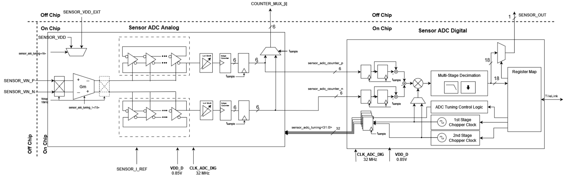
Analog Front-End
Documentation incomplete: Input impedance? Mins and maxs?
Digital Front-End
The delta-sigma ADC’s DSP chain is implemented as a cascaded integrator comb (CIC) decimation filter for noise shaping. The key CIC filter parameters for this design are N=4, R=8000, M=1
Digital Front-End system-level diagram:
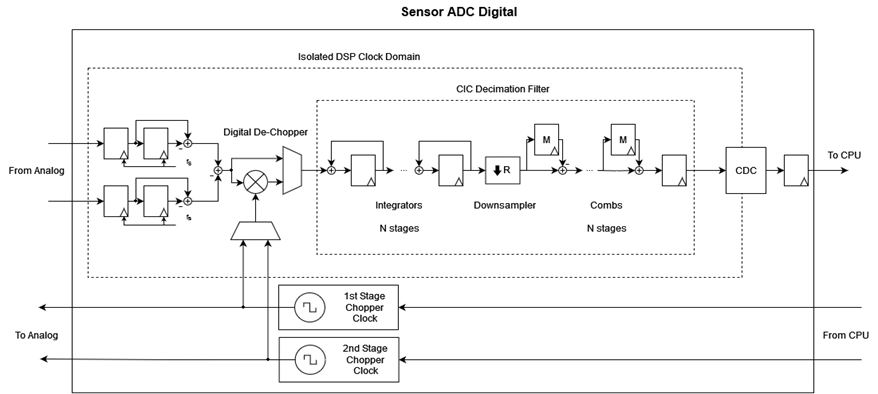
The digital frontend features self-generated, software-programmable chopper clock generators for 1st and 2nd stage choppers. A digital de-chopper/mixer with configurable clock delay to match delay of the analog front-end is also implemented.
Register Map
The base address of the sensor ADC DSP block is 0xB000. All registers in the table below are specified as offsets from the base address 0xB000.
| Register | Name | Size | Function |
|---|---|---|---|
| 0x00 | ADC_STATUS | 32 | ADC_STATUS<11:6> - ADC Counter P ADC_STATUS<5:0> - ADC Counter N |
| 0x04 | ADC_DATA | 20 | Read ADC sample from FIFO |
| 0x08 | ADC_TUNING_0 | 8 | ADC_TUNING_0<5:0> - Current DAC ADC_TUNING_0<6> - BIAS P + ADC_TUNING_0<7> - BIAS N |
| 0x09 | ADC_TUNING_1 | 8 | Reserved |
| 0x0A | ADC_TUNING_2 | 8 | ADC_TUNING_2<0> - Sensor VDD mux select |
| 0x0B | ADC_TUNING_3 | 8 | ADC_TUNING_3<7:0> - Reserved |
| 0x0C | ADC_CHOP_CLK_DIV_1 | 32 | 1st stage chopper clock divider |
| 0x10 | ADC_CHOP_CLK_DIV_2 | 32 | 2nd stage chopper clock divider |
| 0x14 | ADC_CHOP_CLK_EN | 2 | ADC_CHOP_CLK_EN<0> - Enable 1st stage chopper ADC_CHOP_CLK_EN<1> - Enable 2nd stage chopper |
| 0x18 | ADC_DSP_CTRL | 8 | ADC_DSP_CTRL<0> - Enable dechopper in DSP chain ADC_DSP_CTRL<1> - Select chopper clock used in the dechopper ADC_DSP_CTRL<5:2> - Dechopping clock delay, from 0 to 15 cycles |